In this post, I will explain you how to connect Raspberry Pi to a CAN Bus (e.g. your car).
Firstly, know that Raspberry Pi boards aren’t ready out-of-the-box for CAN Bus.
There are +50 Google Search pages about this topic, we can sum up them in two points:
- CAN Bus isn’t supported by Raspberry Pi hardware (GPIO).
- CAN Bus
isn’twasn’t supported by Raspberry Pi software (Raspbian).
TL;DR:
- We will use a bridge between Raspberry Pi and CAN Bus: SPI Bus.
- We will use a CAN controller supported by Linux/Raspbian: MCP2515.
That means that the below instructions are tested “mainly” for MCP251x family.
It’s a widely used component, I may add more CAN controllers in the future.
That said, the theory remains the same for any component that you are using.
If you have any question or remark, I’ll be happy to help you, feel free to leave a comment.
Use the content table below to not waste your time.
1. Hardware
‒‒‒‒1.1 CAN Bus Basics
‒‒‒‒‒‒‒‒‒‒‒‒1.1.1 CAN Wiring
‒‒‒‒‒‒‒‒‒‒‒‒1.1.2 CAN Node
‒‒‒‒‒‒‒‒‒‒‒‒1.1.3 CAN Termination
‒‒‒‒‒‒‒‒‒‒‒‒1.1.4 CAN Controller
‒‒‒‒‒‒‒‒‒‒‒‒1.1.5 CAN Transceiver
‒‒‒‒1.2 SPI Bus Basics
‒‒‒‒‒‒‒‒‒‒‒‒1.2.1 Why SPI?
‒‒‒‒‒‒‒‒‒‒‒‒1.2.2 SPI Wiring
‒‒‒‒1.3 Components
‒‒‒‒‒‒‒‒‒‒‒‒1.3.1 MCP2515
‒‒‒‒‒‒‒‒‒‒‒‒1.3.2 MCP2551
‒‒‒‒‒‒‒‒‒‒‒‒1.3.3 5V to 3V3
‒‒‒‒1.4. Overall Schematic
‒‒‒‒1.5. Bill of Material
2. Software
‒‒‒‒2.1 Why MCP251x?
‒‒‒‒2.2 SPI/CAN Configuration
‒‒‒‒2.3 CAN Utils
3. Tests
1. Hardware
1.1 CAN Bus Basics
1.1.1 CAN Wiring
CAN Bus uses two-wires differential signals.
One is called CAN-H (High) and the other CAN-L (Low).
1.1.2 CAN Node
CAN Bus needs at least two nodes to make the network “up”.
So testing with one node will not work: this is the mistake n°1: Never use only one CAN Bus node.
1.1.3 CAN Termination
CAN Bus needs termination resistors between CAN-H and CAN-L at each end.
Mainly to avoid signal reflections. ISO 11898 recommends the value R=120Ω.
And that’s the mistake n°2: Without termination your CAN Bus will not work correctly.
1.1.4 CAN Controller
CAN Bus is a multi-master protocol, each node needs a controller to manage its data.
CAN controller is connected to the CAN bus using CAN-H and CAN-L.
Example of controllers: MCP2515, SJA100, …
1.1.5 CAN Transceiver
CAN controller needs a send/receive chip to adapt signals to CAN Bus levels.
Controller and Transceiver are connected by two wires TxD and RxD.
Examples: MCP2551, TJA1040…
Regrouping all the above parts:
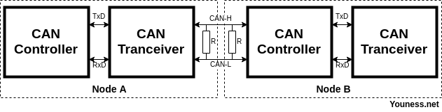
I’ll hide the node B for the rest of the post.
1.2 SPI Bus Basics
1.2.1 Why SPI?
Raspberry Pi doesn’t have a built-in CAN Bus (that’s why we are doing all that…)
But its GPIO includes SPI Bus, that is supported by large number of CAN controllers.
SPI Wiring
SPI Bus uses 4 connections as follow:
- MOSI (Master Out Slave In)
- MISO (Master In Slave Out)
- SCLK (Serial Clock)
Adding to that two other pinouts:
- CS or SS (Chip Select, Slave Select) to enable and disable the chip.
- INT (Interruption) to interrupt the chip when needed.
For that project you don’t really need to know more than that about SPI connections.
Including Raspberry Pi to the previous schematic gives:
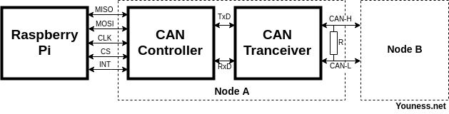
Let’s move now to some practical details.
1.3 Components
1.3.1 MCP2515 (CAN Controller)
Supply:
The MCP2515 can work at 5V or 3V3, so it can be connected to Raspberry Pi GPIO.
Clock:
The MCP2515 needs an external quartz.
For a value of 16Mhz, the datasheet recommends two capacitors of 22pF each.
Pull-up:
Three pins need a pull-up resistor to stay at a recognized level, I took 4K7 (4,7KΩ) resistors. The pins are:
- Pin 17 for Reset.
- Pin 16 for CS.
- Pin 12 for INT.
The SPI bus itself (MOSI, MISO, SCLK) doesn’t need pull-up resistors.
1.3.2 MCP2551 (CAN Transceiver)
Supply:
Contrary to the MCP2515, the MCP2551 can only work at 5V.
That is the mistake n°3: Incorrect voltage levels between IC and Raspberry Pi.
If you connect MCP2515 to MCP2551 directy, the signals will not have the same level.
The 5V-to-3V3 can be done in several ways, as explained for example in this Microchip 3V Tips ‘n Tricks. (see below)
Reset:
We will not need to reset the MCP2551 so the pin 8 can be connected to GND.
1.3.3 5V to 3V3
The easiest way for me is by a resistor divider (voltage divider) between MCP2515 and MCP2551.
We need this divider only for the RxD since here where the 5V will come in.
I used two resistors:
- R1: 10K (10KΩ)
- R2 = 22K (22KΩ)
You can use different values as far as the result is the same with an acceptable current/voltage.
1.4 Overall schematic
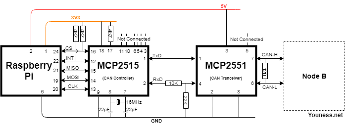
I put the pinout numbers, not the GPIO numbers, I think that it is easier to follow.
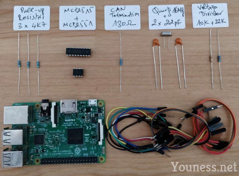
1.5 Bill of Material
2. Software
I’m using Raspbian, and I like to start all the time with a fresh and updated version.
I’m using Raspbian Stretch lite, since we don’t really need a desktop environment.
Update/Upgrade and reboot:
sudo apt-get update
sudo apt-get upgrade
sudo reboot
Usual customizations: Wi-Fi, keyboard, SSH…etc.
If you need specific help for all that, please leave a comment.
2.1 Why MCP251x?
Until some time ago, most of CAN by SPI controllers weren’t supported out-of-the-box by Linux kernels. It was mandatory to compile by yourself the modules and attach them, and this has to be done after every major system update. If you are interested by this part of history, you can read my 2015 post here.
Today things are much easier, Linux kernels added support for MCP251x (and other controllers), so you can directly load them like any other hardware peripheral.
2.2 SPI/CAN Configuration
Enable SPI and overlay it as follows:
sudo nano /boot/config.txt
Uncomment the line:
dtparam=spi=on
After the above line add this:
dtoverlay=mcp2515-can0,oscillator=16000000,interrupt=25
dtoverlay=spi0-hw-cs
The above lines to overlay SPI and set can0 interface to 16MHz, and interruption to GPIO25 pin.
This is the correct way for +4.4.x kernels, the mistake n°4 is to use a deprecated overlay method.
(For earlier versions the overlay may be different)
Save the file: CTRL+X, then Y, then Enter.
Reboot, you can check that the SPI module was started:
dmesg | grep -i spi
By the same command you can check the CAN module is started by default:
dmesg | grep -i can
If for any reason this is not the case, you can add CAN module at system start:
sudo nano /etc/modules
Add “can” in a new line, save the file and reboot.
2.3 CAN Utils
This is the tool to send and receive data.
Install it:
sudo apt-get install can-utils
The two commands that we will use are:
- cansend can0 … to send data.
- candump … to listen to CAN network.
3. Tests
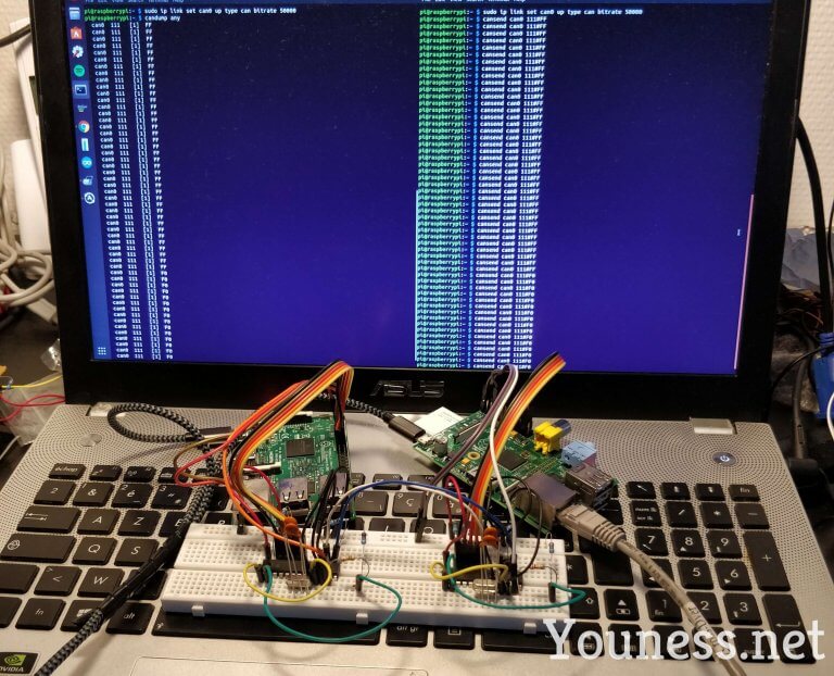
I made two identical nodes A and B (one with Raspberry Pi 3 and one with Raspberry Pi 1)
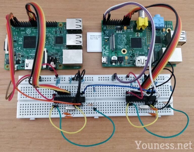
For each one, set up the can0 interface with the same speed:
sudo ip link set can0 up type can bitrate 500000
The 500000, or 50Kb/s to be adapted to the CAN speed of your case.
Set one of them to listen to any CAN message:
candump any
Send something using the other one:
cansend can0 111#FF
The messages are received in the first node:
At this step, you have a Raspberry Pi setup that can be connected to any CAN bus, assuming that you know:
- The CAN Bus location (e.g. the connector in the car).
- The CAN Bus baud rate.
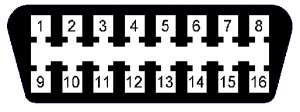
For example, if your car has an OBD2 connector, here are the generic pinouts for CAN Bus:
- OBD CAN-H is pin 6.
- OBD CAN-L is pin 14.
Disclaimer: Please be aware that I’m not responsible for any damage you may have, I’m explaining how to set up a low-voltage project, but when connecting it to your car, you may touch a 12V or create a short circuit. Do it carefully and do it at your own risk.
Disclaimer 2: Never try to send anything to your car using the cansend, until you know what you are doing!
Useful links:
Raspberry Pi GPIO Pinout: http://pinout.xyz/
MMCP2551 Datasheet: http://www.microchip.com/mcp2551
MCP2515 Datasheet: http://www.microchip.com/mcp2515
SPI Bus: https://en.wikipedia.org/wiki/Serial_Peripheral_Interface_Bus
Diagrams done with Draw.io
[…] on how to connect Raspberry Pi to CAN Bus. http://youness.net/raspberry-pi/raspberry-pi-can-bus. […]
Great write up.
While I’m sure many appreciate the details of the circuits involved, I’d bet others would appreciate knowing a Pi hat exists for this purpose.
SKPang had the PiCAN2 board which I’ve used extensively for the past 3 years in various projects. He has single and dual bus board as well as a variety which includes a 12v to 5v SMPS that works great for vehicle projects.
Note: I’m not affiliated with SKPang other that being a customer.
I had the same idea when I listed CAN Bus shields for Raspberry Pi in my other blog 3 years ago: http://tiqni.com/raspberry-pi/raspberry-pi-shields-for-can-bus
Thanks for your comment.
Youness, thanks! That’s what I get for not browsing your blog more… 😉
Thank you so much, such a great blog
Your’e welcome Yahya la chokr 3ala wajib.
[…] How to Connect Raspberry Pi to CAN Bus […]
Thanks for that great tutorial! I did build the circuit and when plug it over a CAN BUS network based on two Arduinos and MCP2515/TJA1050 raspberry pi read data flow appropriately. But I have one question: Why loopback mode didnt works for me? There are some configurations or modifications on to circuit to get it working? Maybe someone can help me! Thanks…
I don’t think there is specific things to do for loopback mode since you will communicate inside the MCP2515 but I let others answer it if they know.
Thanx for the great HowTo.
Just a remark for a tiny mistake:
The drawing in chapter 1.1.5 has a bug. The Node B must be twisted. The CAN Transceiver should be connected to the bus and being on the left side, the CAN controller should be on the right side.
Oups, this what happens when you copy/paste too much… Thanks for the remark.
Hi,
Should this same process work for the microchip CAN bus analyzer (USB) ?? I followed these steps and after “ip link set can0….” i get
cannot find device “can0”
Product details: https://www.microchip.com/Developmenttools/ProductDetails/APGDT002
I have this device and it works when running under windows. I am trying to monitor some canbus industrial equipment (not a car, data not encrypted).
Thanks for any help.
Do you mean connecting this CAN analyzer to Raspberry Pi through USB? If so the answer is no, the software provided works only for Windows, and I don’t know if it is possible to extract needed drivers to put them on a Linux environment…
Yes, i meant using USB. 🙁
Thanks for the help.
I did a quick search, in this link maybe you will find how to add it to Raspberry Pi : https://github.com/rkollataj/mcba_usb/blob/master/README.md
Built and working.
Small correction: the schematic in 1.4 is wrong (but the images are correct) Raspberry pin 20 is actually pin23 (Sclk)
( Pin 20 is ground. )
I’m having some issues after following this guide.
can0 interface shows as state UNKNOWN on both pi’s after booting.
can0: mtu 16 qdisc pfifo_fast state UNKNOWN group default qlen 10 link/can.
If I set both to down and bring them back up, one usually always comes UP, sometimes both come UP. At the moment, neither are coming up, just staying as UNKNOWN.
dmesg | grep -i can and dmesg | grep -i spi on both pi’s show the following:
mcp251x spi0.0 can0: MCP2515 successfully initialized.
cansend and candump show nothing whatsoever.
Wireshark shows the following on the pi I am sending from:
1 0.000000000 CAN 32 STD: 0x00000111 ff
2 0.000296441 CAN 32 ERR: 0x00000004 00 20 00 00 00 00 00 00
3 0.001137634 CAN 32 ERR: 0x00000040 00 00 00 00 00 00 00 00
If I do the same on the other pi, I get this:
1 0.000000000 CAN 32 STD: 0x00000111 ff
2 0.001802927 CAN 32 ERR: 0x00000004 00 10 00 00 00 00 00 00
3 0.002334128 CAN 32 ERR: 0x00000004 00 20 00 00 00 00 00 00
4 0.004644923 CAN 32 ERR: 0x00000040 00 00 00 00 00 00 00 00
After trying wireshark, checking dmesg again, I end up with bus-off error:
mcp251x spi0.0 can0: bus-off
Any pointers on what to check next??
I’ve never faced this issue, my easy advice all the time is to restart from scratch even if it can a waste of time, sometimes a small detail may create this, like setting incorrect baudrate.
It looks like my issue was a bad connection somewhere.
I bought some better quality breadboards with better gripping sockets, as I thought the first pair I was using let some of the leads flop around a bit too much for my liking.
I rebuilt the pair of modules on the new breadboards and it all worked first go.
Just goes to show, when something doesn’t work, start with the basics first.
Thanks for the write up.
Thanks for the feedback, cool that’s solved now.
Is there a way to read the MCP2515 registers? Not sure how much low level access linux’s socket interface provides! I’m interested in seeing what the values are, especially the timing configuration bits.
This has been great help.
At first I got some errors but turned out the wiring problems.
Thank you so much.
Hey, nice job! But why 130 Ohms? Can BUS standards recommend resistance at ends of 120 Ohms…
And the clock, datasheet recommends two capacitors of 22 pF for CERAMIC RESONATORS (Not for CRYSTAL OSCILATORS). Anyway they are insignificant details, your work is very well documented.
Congratulations!
Hi,
Yes I mentionned that the recommended value is 120 but I had only 130 those days.
The same for capacitors. That said it works good if you have any of those components I can confirm that it is OK.
Hi again!
Do you have any idea to implement CAN BUS FD (MCP2517FD, MCP2558)?
Thank you very much in advance!
I don’t know sorry.
Hi,
Thanks alot.
I connected mcp2515 to raspberry pi3,but dont know what libraries i need to include in program.can you please send any demo program to blink led or control fan.Please send asap…..
Hi, I don’t have a demo to give you, but I suggest that you connect LEDs (with resistor) between CAN-H (CAN-L) and GND (3V3) and send any data, they will blink because there will be voltage differences, it is the principle used by CAN analyzers to see that it is transferring data.
I’m looking to attach a pican2, and then create a service / constantly running script that read from it and writes output to the rpi as specific keyboard strokes that can be picked up by the rpi. Anyone have any direction they can point me to?
Hi team,
can we load AUTOSAR Stack into the board using debugger?
if it is Yes
can some give help on that
it will be helpfull for me
I’m not sure the Raspbian OS is compatible with AUTOSAR.
hello!
nice article, thanks for the info!
i think there is a bug in the schematic, with the voltage divider:
the 22k should be placed between the 10k and the mcp2515.
best regards,
Hi Wanek,
lol you’re right, I’ll try to find the schematic to modify it. Thanks for your correction!
Thanks youness for your great tutorial
I’m trying to make the MCP2515 work like on this tutorial but it is not working and can’t figure out what is the problem, since the MCP2515 is successfully initialized so the wiring is correct and can0 is is up and everything is good but can’t see any traffic ( sending nor receving: i hooked an arduino to it which sends messages in a loop)
pi@raspberrypi:~ $ dmesg | grep -i spi
[ 6.301058] mcp251x spi0.0 can0: MCP2515 successfully initialized.
pi@raspberrypi:~ $ sudo ip link set can0 up type can bitrate 500000
pi@raspberrypi:~ $ candump can0
^Cpi@raspberrypi:~ $cansend can0 456#43414e2054657374
I was suspecting the the MCP2515 is bad but I tried it on arduino and it works fine both receiving and sending ( two arduinos one sending and one receiving, the one sending is also the one I connected to RPI to send messages to it also tried receving but nothing works.)
I want to use RPI so I can use Linux can-utils but unfortunetly this didn’t work for me
Can you figure out what is the problem or how to debug this to find out what is the problem.
Thanks
The problem is the voltage levels, the Arduino is using 5V while Raspberry Pi is 3.3V. It is normal that you don’t get data between them because the logic level of “1” is different.
Try to have Arduino with 3.3V I think it is possible.
Why does Arduino voltage matters ? Since the the mcp2551 of the raspberry pi is hooked to 5v so it has 5v voltage levels like the Arduino not 3.3v
So i think both CAN nodes have 5v voltage levels, am I right ?
No, Raspberry Pi GPIO is based on 0V and 3.3V only, to say 0 and 1. If it receives 5V this may cause damage or at least will not work.
Hi, Pin 8 of the MCP2551 ist not reset, see datasheet.
“Pin 8 (Rs) allows three different modes of operation to be selected: High-speed, Slope control and Standby.
For high-speed operation, the transmitter output transistors are simply switched on and off as fast as possible. In this mode, no measures are taken to limit the rise and fall slopes. A shielded cable is recommended to avoid RFI problems. High-speed mode is selected by connecting pin 8 to ground.
Slope control mode allows the use of an unshielded twisted pair or a parallel pair of wires as bus lines. To reduce RFI, the rise and fall slopes should be limited. The rise and fall slopes can be programmed with a resistor connected from pin 8 to ground. The slope is proportional to the current output at pin 8.
If a HIGH level is applied to pin 8, the circuit enters a low-current Standby mode. In this mode, the transmitter is switched off and the receiver is switched to a low current. If dominant bits are detected (differential bus voltage >0.9 V), RXD will be switched to a LOW level. The microcontroller should react to this condition by switching the transceiver back to normal operation (via pin 8). Because the receiver is slower in Standby mode, the first message will be lost at higher bit rates.”
So connecting it to GND will not harm. Just for clarification.
Thank you.
Hi,
I used a Pi 3B+ and a CAN-BUS shield for Arduino. I used method described here. The only mistake that I might do was providing a 5V to mcp2515 in my first day connecting. If I typed : uname -a, it returned:
Linux raspberry 4.19.75-v7+ #1270 SMP Tue sep 24 18:45:11 BST 2019 armv7 GNU/Linux
I also revised config.txt as the author wrote here. Now I changed 5V to 3.3v. However, when I typed : dmesg | grep -i spi, it returned:
mcp251x spi0.0: cannot initialize Mcp2515. Wrong wiring?
mcp251x spi0.0: Prob failed, error=19.
Then I typed ‘ls /dev/spidev0.*’ It returned :
/dev/spidev0.1
How can I check the spi work or not? Thanks.
I think you should check the schematic of this shield and how the GPIO of the Raspberry Pi is connected to the two MCP, it is not all the time compatible with both Arduino and Raspberry Pi.
I used a board designed by myself which applied MCP2515 and NXP A1050. I provided 5V to them. Initialization is success, both of MCP2515 and can0. However, when I type ‘sudo ip link set can0 up type can bitrate 500000’, there is no ‘$’ in the next row. How to solve this new problem? Thank you.
What do you mean by $? The symbol for normal Linux user?
How do i make this work with kernel 4.19?
It gives me an error “cannot find device can0”
Check again your schematic between the Raspberry Pi and the MCP2515 and its power supply.
Hi Youness
I am using the SK Pang board on board my boat and am getting NMEA 2000 data using the software supplied by SKP. I now need to retrieve from this, for example, depth and process this using for preference Python. Can you point me towards the software required to do this? Your help would be appreciated.
Hi,
Sorry for late answer.
I think that it uses can-utils. So to read data you just need to execute the command: candump. You need to know the ID for depth and process to look for them in the dump log.
Question: why on photos you put capacitador on parallel connection ??
it should not be in series connection like the diagrams shows?
Thanks for the answer.
Each capacitor is between a quartz pin and GND, if you zoom you will see they are connected to black wire GND. They are not in parallel or in serie.
First of all, thank you for your quick answer.
then … the connection would be as shown in this image http://www.electronoobs.com/images/Arduino/tut_43/atmega8_2.png ?
Second question: It is the breadboard used a model called “full breadboard” (the long row of holes are no connected- divided by the gap in the middle).
In that page, the second type http://wiki.sunfounder.cc/index.php?title=Breadboard_Basics_–_Types.
Thank you very much, I really appreciate it 🙂
First of all, thanks for the quick reply.
Ok, to ensure that we understand each other… is the capacitor connection like this? (http://www.electronoobs.com/images/Arduino/tut_43/atmega8_2.png).
On the other hand, when carrying out the project, I realized that this is the breadboard model, right? (Protoboard model Full, no Full + http://wiki.sunfounder.cc/index.php?title=Breadboard_Basics_–_Types)
Thanks for the answer 🙂
First of all, thanks for the quick reply.
Ok, to ensure that we understand each other… it is the connection like this? (http://www.electronoobs.com/images/Arduino/tut_43/atmega8_2.png).
On the other hand, when carrying out the project, I realized that this is the breadboard model, right? (Protoboard model Full, no Full + http://wiki.sunfounder.cc/index.php?title=Breadboard_Basics_–_Types)
Thanks for the answer 🙂
Yes the connection of the capacitors in the picture you attached is correct.
For the board I used, the upper lines are not connected. I mean that the supply 5V, 3V3 and GND of each Raspberry is separated, I did that to be able to disconnect one Raspberry without impacting the supply of the other one.
Feel free to ask any other question I’m here to answer it as soon as I can 😉
again, thanks for the quick reply 🙂
I am understanding everything little by little, thanks for the patience.
I have other question, related to the voltage level. In the image attached to the link (https://ibb.co/WBrPpyc uploaded by me) I have only mounted the voltage divider to ask you if it would be well connected.
Blue resistor: 22k
White resistor: 10k
Hi !
I have a problem in the software point.
I put every electronic connection like the post and i think it is ok but when I configure the software part of the raspberry, I get the following comments:
dmesg | grep -i spi
mcp 251x spi0.0 : MCP251x didn’t enter in conf moder after reset
mcp251x spi0.0: Probe failed, err = 16
mcp251x; probe of spi0.0: Probe failed with error -16
More information in this image: https://ibb.co/4PvbLYC
Do you know what kind of error can be treated and how could it be solved?
Thanks my friendo
Something?
Hi friend,
I got a question for you:
when i put this
• dmesg | grep -i spi
• dmesg | grep -i can
• sudo ip link set can0 up type can bitrate 500000
And then ifconfig to check the connections I see that in the two RP i receive two different answers. One of the two, i think it is OK:
can0: flags=193 mtu 16…
but in the other i recieve the next message:
can0: flags=128 mtu 16…
why i recieve two different message??
I don’t know, but for me this is not a message, a message is what you send from one board to the second with the command cansend.
Hi,
I hope you still answer to comment.
You post is really awesome. It’s clear !
I need to communicate on CAN Bus at work, and I will higly probably use your diagrams, and your informations to understand what I’m doing !
Do you know if we can dynamically change CAN Speed ?
When I start my system, every components communicate at 250kb/s. After an authentification step, a kind of master on BUS, says to all slaves the new speed ( It can be 500kb/s or 1mb/s).
Hello Alexandre,
I try my best to answer comments when I receive them
From my experience, I needed to set the can0 interface down and then up in order to change the speed, so it wasn’t dynamically. In addiction, I don’t see why you need to do that change, is it a constraint linked to the authentication step?
Hello,
I have 2 Raspi having HAT controller on each of them. I assume that MCP2512 is already in-built in the controller and so I use a CAN bus wire to connect the H and L ports of both setup. I used candump and cansend commands but I don’t get the data displayed. However the commands work when the loopback is on. Could you let me know what could be the issue?
Hi, I spotted another error in your schematic (unfortunately only after I designed a custom PCB according to the schematic and was wondering why I have too low voltage on the RxD pin at the MCP2515):
The 10kOhm resistor for the voltage divider between MCP2515 and MCP2551 RxD pins needs to be at the MCP2515-side such that the current passes the 10kOhm resistor first when travelling out of the MCP2551 and then split up between direct trace to MCP2551 RxD pin and GND via 22kOhm.
I hope this helps one or the other here!
Otherwise: Thanks for the write-up!
Sorry, too late, too tired:
I meant “The 10kOhm resistor needs to be at the MCP2551(!)-side …”
THANK YOU for the effort on this Youness and everyone else.
My interest is more in using the Pi as a main ecu with many canbus nodes.
I like the car stuff, I have done that before with PC Tactrix 2 and excellent help
from the romraider community.
I hope I can contribute a little here in the near future.